





Automatic Production Equipment of Polymer Battery for Mobile Phone Battery Pack Production Line
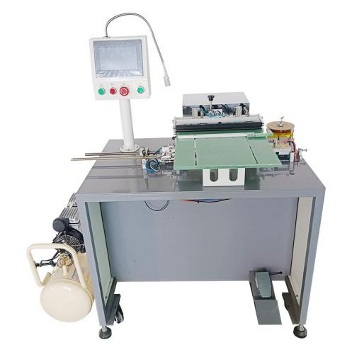
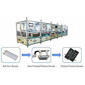
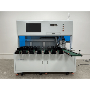
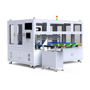
Automatic Production Equipment of Polymer Battery for Mobile Phone Battery Pack Production Line 1.Equipment Function Introduction The automatic production line is mainly used to complete the mobile phone battery pack production process. The process flow includes: 1)Polymer battery tab shaping , 2)OCV test, 3)Battery tab cutting, 4)Welding, 5)Double-sided adhesive pasting, 6)BMS bending, 7)Adhesive pasting and forming, 8)Finished battery testing; 9)FPC sponge adhesive pasting. According to the process flow and technical requirements, the pack line is connected by the following 5 equipment: (1)Automatic feeding + multifunctional machine; (2)Automatic laser welding machine; (3)Double sided adhesive tape + L-shaped nickel sheet bending + protective plate bending machine; (4)Automatic head adhesive machine. 2.Process Flow 3.Technical Parameters 1. Applicable Range of Battery Size (unit: mm): Length: 40-130mm (Excluding pole lug length) Width: 30-70mm Thickness: 3-10mm Lug length: 4-20mm 2. Environmental Conditions: Air Pressure of Air Source: 0.5 ~ 0.6 MPa Power Supply Voltage: 220V, 50Hz Total Power: ≤15kw Area Bearing Ratio: ≤500kg / M² Ambient Temperature: 5ºC-50ºC Humidity: 50% - 90% 3. Production Line Efficiency: ≥900pcs / h 4. Equipment Utilization Rate: > 98% 5. Product Qualification Rate: > 98% 6. The feeding and discharging directions of the equipment shall be consistent, and the tail of the electric core shall face the equipment operation surface. 7. Process Applicability: Applicable to soft pack batteries with the same process. 8. Meet safety production requirements, including product safety and battery safety. 9. Overall Dimension (Excluding assembly line): Wire body: 9200 (Long)*1200 (Width)*1900 (Height) mm Assembly Line Height: 900mm±50mm 4.Overall Equipment Layout and Equipment Workflow Description Overall Layout of Line Body: Note: the line includes 4 persons, one of whom is responsible for the laser machine protection board; 2 persons are responsible for installing the rubber shell; One person is responsible for feeding, inspecting the whole line and replacing materials such as tape. Function and Action Requirements of Single Equipment: (1)Automatic Feeding + Multifunction Machine: 1) Functional Action ① The battery is automatically loaded from the feeding tray to the assembly line of the feeding machine through the feeding machine, and the positioning cylinder is positioned; ② The shift manipulator grabs the battery from the loading machine assembly line to the multi-function machine feeding assembly line. The battery can be rotated by 90°or turned over at will; ③ The electric core enters through the feeding assembly line of the multi-function machine. After the electric core is positioned, it is grabbed to the feeding station of the rotary table by the feeding manipulator; ④ The rotary table rotates clockwise to enter the primary pole ear shaping station for pole ear shaping; ⑤ Rotate the rotary table clockwise to enter the test station, test the voltage internal resistance, scan the code and upload the data; ⑥ The rotary table rotates clockwise to enter the left tab cutting station to cut the left tab; ⑦ The rotary table rotates clockwise and enters the cutting station of the right tab to cut the right tab; ⑧ The rotary table rotates clockwise; Enter tab secondary plastic surgery, polar ear plastic surgery; ⑨ The rotary table rotates clockwise to enter the battery discharge station, discharge the battery, and grab it to the feeding line of the equipment; The cell rotates 90°and then turns 180°. 2) Technical Requirements ① Capacity (UPH): ≥1200pcs / h ② Equipment utilization rate: > 98% ③ Qualified rate: > 99.5% ④ Deviation range of pole lug cutting length: ±0.2mm ⑤ Cutter life ≥400000 times ⑥ Voltage test accuracy:±0.01% rdg. ±3dgt(According to the accuracy of the tester); ⑦ Internal resistance test accuracy:±0.5% rdg.±5dgt(According to the accuracy of the tester); ⑧ Misjudgment rate: it must be 100% in channel OK products and≤0.3% in channel ng products; ⑨ Scan the code of the cell, bind and upload the test data; ⑩ The material can be taken from the stacked plastic suction tray. The tray cannot be connected with the tray. The battery cannot be damaged during the reclaiming process. The empty tray after taking the material will be removed automatically and sorted into a stack; ⑪ Overall dimension (excluding assembly line): 2200 (Length)*1200 (Width)*1900 (Height) mm. ⑫ Material size: Note: The load of electric core loading lifting table is less than or equal to 40kg. Name Length (mm) Width (mm) Thickness (mm) Remarks Suction Plastic Tray 270-420 mm 215-350 mm Stacking height of multiple layers ≤ 250mm The number of electric cells in each panel is 2-8 Battery 40-140mm 35-80mm 3-8mm 3) Key Configuration ① Tester: Lanqi BK600A, 1 set ② Scanning gun: Honeywell, 1 set (2) Laser Welding Machine: 1) Functional Action ① The battery enters the laser machine through the feeding assembly line, is grasped by the feeding manipulator to the secondary positioning, and the battery rotates 90°; ② The loading manipulator grabs the battery from the secondary positioning to the turntable loading station, and the battery rotates 45°; ③ The rotary table rotates counterclockwise to enter the pole ear shaping station for pole ear shaping; ④ The rotary table rotates counterclockwise and enters the feeding station of the protection plate to load the protection plate; ⑤ The rotary table rotates counterclockwise and enters the protection plate positioning station to position the protection plate; ⑥ The rotary table rotates counterclockwise to enter the laser welding station for laser welding; ⑦ The rotary table rotates counterclockwise to enter the battery discharge station, discharge the battery, and grab it to the feeding line of the equipment. 2) Technical Requirements ① Capacity (UPH): ≥1200pcs / h; ② Equipment utilization rate: > 98%; ③ Qualified rate: > 99.5%; ④ Position accuracy of laser welding: ±0.02mm; ⑤ Check the welding position of the protective plate and the electrode lug of the electric core, and the position accuracy: ±0.1mm; ⑥ Pre judgment of spot welding (weld when the protective plate and the electrode lug of the electric core are placed OK, and pick them out without welding when NG); ⑦ Welding firmness standard: tensile force of nickel and nickel materials≥2kgf, tensile force of aluminum and nickel materials≥0.6kgf; ⑧ The positive and negative ear energy of laser welding can be set separately and switched freely (Note: the laser machine manufacturer is responsible for this item, and the wire body manufacturer is responsible for triggering the connection, etc.); ⑨ Overall dimension (excluding assembly line): 1200 (Length)*1200 (Width)*1900 (Height) mm. ⑩ Material size: Name Length (mm) Width (mm) Thickness (mm) Remarks Protective Plate 25-80 mm FPC sagging 5-30 mm 0.6-1.2mm (3)Double Sided Adhesive Tape + L-shaped Nickel Sheet Bending + Protective Plate Bending Machine: 1) Functional Action ① The battery enters the double-sided adhesive tape + L-shaped nickel sheet bending + protective plate bending machine through the feeding assembly line. After the electric cell is positioned, it is grabbed to the turntable loading station by the feeding manipulator; ② Rotate the rotary table counterclockwise to enter the gluing station to complete the gluing of double-sided adhesive at the cup mouth; ③ The rotary table rotates counterclockwise and enters the L-shaped nickel sheet bending station to bend the L-shaped nickel sheet; ④ The rotary table rotates counterclockwise and enters the shaping station to shape the L-shaped nickel sheet to ensure the fit; ⑤ The rotary table rotates counterclockwise to enter the FPC shaping station to shape the FPC; ⑥ The rotary table rotates counterclockwise to enter the protective plate bending station and bend the protective plate 90 ° ⑦ The rotary table rotates counterclockwise and enters the battery discharge station. The battery discharge is directly grabbed by the manipulator to the feeding assembly line of the equipment; ⑧ After manually completing the processes of manually installing rubber shell, manually folding protective plate and manually folding soft and hard combination plate on the assembly line, the battery flows into the equipment. 2) Technical Requirements ① Capacity (UPH): ≥1000pcs / h; ② Equipment utilization rate: > 98%; ③ Qualified rate: > 99.5%; ④ Inner diameter of double-sided adhesive cylinder (mm):∅76; ⑤ Gluing accuracy: ±0.25mm; ⑥ Bending angle: less than or equal to 90; ⑦ The electric core, protective plate and its components shall be protected to prevent damage; ⑧ Overall dimension (excluding assembly line): 1200 (Length)*1200 (Width)*1900 (Height) mm. (4) Full Automatic Head Gluing Machine: 1) Action Function ① The battery enters the head gluing machine through the feeding line. After the electric cell is positioned, it is grabbed to the turntable loading station by the feeding manipulator; ② Rotate the rotary table counterclockwise to enter the head gluing station and stick the forming glue on the upper surface of the battery; ③ Rotate the rotary table counterclockwise to enter the glue wrapping station and wrap the ears on both sides of the molding glue on the back of the battery; ④ The rotary table rotates counterclockwise to enter the glue wrapping station and wrap the top of the head forming glue to the back of the battery; ⑤ The rotary table rotates counterclockwise to enter the battery discharge station, discharge the battery, and grab it to the feeding line of the equipment. 2) Technical Parameters ① Capacity (UPH): ≥1100pcs / h; ② Equipment utilization rate: > 98%; ③ Qualified rate: > 99.5%; ④ Inner diameter of double-sided adhesive cylinder (mm): ∅76; ⑤ Gluing accuracy: ± 0.25mm; ⑥ Overall dimension (excluding assembly line): 1400 (Length)*1200 (Width)*1900 (Height) mm. 5.General Requirements for Equipment (1) General Use Requirements 1) Each station equipment can select independent operation or binding operation and save data according to the requirements of each module. 2) The tooling fixture can be replaced and is applicable to other models of products. 3) Easily worn parts must be replaceable separately. 4) Anti skid treatment must be carried out for the screws in the stations with high equipment activity and strength, and dental braces shall be installed on the screw holes on bakelite and other parts. 5) Avoid or protect the parts that can damage the electric core, such as falling, crushing, scratching, welding, etc. 6) The electrostatic treatment of the whole equipment shall meet the requirements of the company, and the contact parts of the protective plate shall be made of anti-static materials. 7) Each equipment shall be equipped with lighting facilities separately, and energy-saving lamps are required. 8) Product protection and quality control: ① Not lower than the requirements of existing manual line operation (see product process flow chart for details). ② The operation process requires that the battery bar code is bound to realize card closing to avoid missing processing and outflow of defective products. (2) Mechanical Safety Requirements 1) Comply with national safety standards and national safety and health regulations. 2) The equipment shall be provided with good and comprehensive safety protection measures, such as protective net, photoelectric protection, protective grating and other protective devices. The rotating parts, dangerous parts and dangerous parts on the equipment shall be provided with protective devices. 3) Protective devices and other facilities shall prevent operators from entering the operation dangerous area, or when personnel enter the dangerous area by mistake, the equipment can perceive the corresponding protective action, which is unlikely to cause injury to personnel, that is, the protective devices shall realize linkage and interlock with the equipment control system. 4) Movable parts and components that are frequently adjusted and maintained shall be equipped with movable protective covers. If necessary, interlocking device shall be installed to ensure that movable parts cannot be started without closing the protective device (including protective cover, protective door, etc.); Once the protective device (including protective cover, protective door, etc.) is opened, the equipment shall stop automatically immediately. 5) The transmission, action, radiation and other parts of the equipment shall have good screen protection devices. 6) The operating mechanism of the equipment, such as handle, hand wheel and pull rod, shall be set with convenient operation, safety and labor saving, clear, complete, firm and reliable marks. (3) Electrical Safety Requirements 1) The control system can ensure that the energy supply of the equipment will not cause danger in case of abnormality, and the equipment itself will not be damaged or hurt personnel. 2) The control system shall be far away from flammable, explosive, high temperature, high humidity and high corrosion areas. If it is unavoidable, necessary shielding measures shall be set, and the control cabinet shall have good heat dissipation conditions. The control line shall ensure that it will not cause harm even if the line fails or is damaged. 3) The control system shall be placed at the position convenient for operation and observation by the operator. The equipment is equipped with necessary emergency stop buttons according to specific conditions. The emergency stop mechanism must be self-locking, and its operation color is red. If there is a background color, the background color shall be black. The operating parts of button operated switch shall be palm push type or mushroom head type. 4) Electrical control system of equipment: with overload protection and short circuit protection functions. 5) During inspection, adjustment and maintenance, the production equipment that needs to observe the dangerous area or parts of the human body need to extend into the dangerous area must be prevented from misstartup. When the equipment may endanger personal safety due to accidental start, mandatory safety protection devices must be configured to prevent accidental start. 6) When the energy is cut off accidentally and then switched on again, the equipment must be able to avoid dangerous operation. 7) The three-phase five wire power supply system is adopted, and the protective neutral connection measures are adopted for the equipment shell. 8) During the operation of the equipment, when a component fails or is damaged, the equipment itself has corresponding protective measures, which can not cause greater damage to the equipment itself or harm the operator. Protection measures mainly include: action running time protection: when the actual running time of an action exceeds the normal value, it will give an alarm; Misoperation protection: due to the lax sealing and pressure relief of the pipeline, there shall be an alarm when the parts that should not act act act. 9) There are measures to prevent wire wear around the outlet of the distribution cabinet, and there is no connector in the middle of the power line. 6.Brand and Packing List of Important Parts (1) Brands of Important Parts: NO. Standard Part Category Description of Function and Brand Restrictions 1 Frame Surface paint baking treatment 2 Big Board The surface shall be electroplated with a thickness of 20mm 3 Machined Parts Sand blasting and oxidation treatment for aluminum parts and electroplating treatment for iron parts 4 Man-Machine Brand limited to vialon 5 PLC Omron has a three-year warranty and reserves 10% ports 6 Power Supply Omron, Delta, Mingwei and other switching power supplies 7 Sensor Panasonic, Kearns, Omron 8 Electric Control Accessories Wiring bar and other electrical parts shall be at least domestic high-quality brands 9 Contactor Schneider, Omron 10 Button Schneider, Omron 11 Ordinary Motor Xintaichuang 12 Stepper Motor Reyes 13 Servo Motor Panasonic, Fuji 14 I / O Board Lesai, Ni, Gugao 15 Ordinary Cylinder Yadeke, SMC 16 Rodless Cylinder Yadeke, SMC 17 Solenoid Valve Yadeke 18 Gas Source Treatment Combination Yadeke 19 Bearing or Linear Bearing Mismi, NSK, THK and other brands 20 Guide Shanghai Bank, THK and other brands 21 Linear Module Shanghai silver, Mismi and other brands 22 Structural Standard Parts Shanghai silver, Mismi and other brands 23 IPC Yanxiang 24 Monitor Philips (2) Packing List NO. Name Quantity Remarks 1 Packing List 1 copy 2 Certificate of Conformity 1 copy 3 Operation Manual 2 copies 4 Machining Drawing of Vulnerable Parts 1 copy 5 Electrical Schematic Diagram 2 copies Electronic file 6 Schematic Diagram of IO Connection 2 copies 7 Equipment Maintenance Manual 1 copy 8 List of Vulnerable Parts 1 copy Electronic file 1. We supply machines with battery technology support. 2. We supply full set of lithium battery equipment for lab research, pilot scale research and production line. 1 Standard exported package: Internal anticollision protection, external export wooden box packaging. 2 Shipping by express, by air, by sea according to customers' requirements to find the most suitable way. 3 Responsible for the damage during the shipping process, will change the damage part for you for free.

 Online service
