High Quality Battery Electrolyte LiPF6 NaPF6 LiFePO4 LiNiMnCoO2 For Lithium-Ion Materials Research
Contact Person:Louis Yang Email: Louis@chinabatterymachine.com Tel:+86 13003860308 Whatsapp: +86 13003860308 Wechat:18659217588

Email: Louis@chinabatterymachine.com
Tel:+86 13003860308
Whatsapp: +86 13003860308
Wechat:18659217588
Item No.:
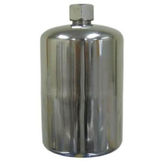
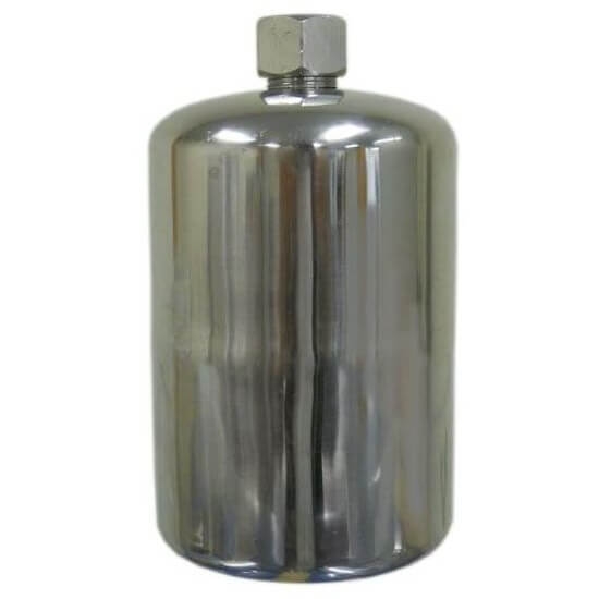
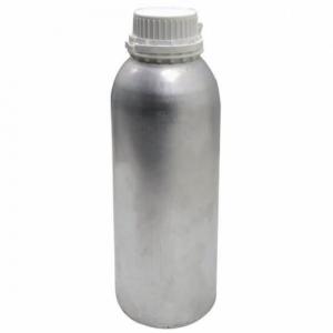
LITH-Stainless-SteelHigh Quality 1000ml Stainless Steel Bottle For Battery Electrolyte Research
Material: Stainless Steel for Corrosive-proof
Bottle Thread: 28mm for standard bottle adapter
Cap: Hex Angular (should be tighten by wrench)
Volume Capability: 1000mL
Net Weight: 0.5 lbs

Contact Person:Louis Yang Email: Louis@chinabatterymachine.com Tel:+86 13003860308 Whatsapp: +86 13003860308 Wechat:18659217588
Contact Person:Louis Yang Email: Louis@chinabatterymachine.com Tel:+86 13003860308 Whatsapp: +86 13003860308 Wechat:18659217588
Contact Person:Louis Yang Email: Louis@chinabatterymachine.com Tel:+86 13003860308 Whatsapp: +86 13003860308 Wechat:18659217588
Contact Person:Louis Yang Email: Louis@chinabatterymachine.com Tel:+86 13003860308 Whatsapp: +86 13003860308 Wechat:18659217588
Contact Person:Louis Yang Email: Louis@chinabatterymachine.com Tel:+86 13003860308 Whatsapp: +86 13003860308 Wechat:18659217588
Contact Person:Louis Yang Email: Louis@chinabatterymachine.com Tel:+86 13003860308 Whatsapp: +86 13003860308 Wechat:18659217588

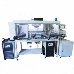
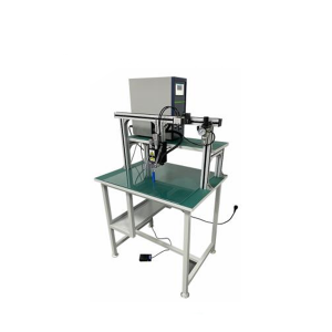
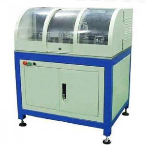
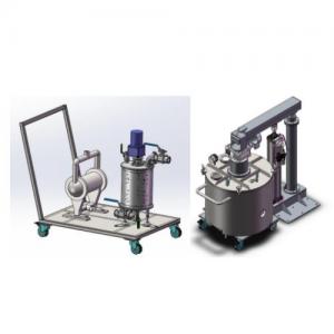
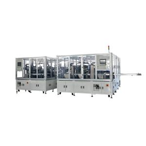
Lith Corporation, founded in 1998 by a group of material science doctor from Tsinghua University, has now become the leading manufacturer of battery lab&production equipment. Lith Corporation have production factories in shenzhen and xiamen of China.This allows for the possibility of providing high quality and low-cost precision machines for lab&production equipment,including: roller press, film coater,mixer, high-temperature furnace, glove box,and complete set of equipment for research of rechargeable battery materials. Simple to operate, low cost and commitment to our customers is our priority.
Contact Us Online service
 Louis@chinabatterymachine.com
 +8618559646958